An Overview of Weft Insertion Elements in Air Jet
Last updated on August 29th, 2023 at 11:06 pm
Weft Storage System – Drum Feeder
The following figure shows the schematic diagram of a drum feeder for air-jet weaving machines. The weft yarn is drawn off the package and wound onto measuring band two by the rotating motion of yarn guiding tube 1. The pick length depends on the fabric width. The pick length is set by adjusting the measuring bands and the number of coils. The electromagnetically controlled stopper pin 3 releases the weft yarn at the machine angle set.

Sensor 4 controls the number of coils to be unwound. As soon as the parameterized number of coils is drawn from the drum feeder, the stopper pin blocks the following coils. The pick length is fine-tuned by adjusting the measuring bands on the drum feeder.
The electronically controlled filling feeder guarantees exact metering of the required filling yarn length, thus ensuring a minimum of filling yarn waste. High filling insertion rates inevitably entail high peak values of tensile stress when the filling yarn is slowed down. The electronically controlled filling yarn brake system reduces peak values of the yarn tension forces considerably, as shown in Figure. As a result, there are fewer machine stops, particularly when weaving coarse and delicate yarns.

In some machines, the rotation of the yarn guide in the drum feeder is synchronized with the rotation of the weaving machine. The solenoid pin for filling release is controlled by the computer. Therefore, there is no need to adjust the drum when changing the weaving machine revolution.
Main Nozzle
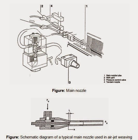
The filling yarn threaded into nozzle tube one is accelerated by the concentrated air jet and inserted into the shed. The air needed depends on the yarn structure and the yarn count. It is controlled using pressure control valve 3. A weak air stream is blown onto the yarn lying in the main nozzle to keep the motionless pick tensioned. The air volume needed for this purpose can be individually controlled.
To reduce the weft insertion time, a tandem nozzle four is used, the equivalent of two main nozzles positioned behind each other. The tandem nozzle has the job of unwinding the weft yarn from the drum feeder. The tandem nozzle thus compensates for the winding resistance. The pressure can be reduced at the main nozzle, assuring gentle yarn insertion.
Relay Nozzle Unit
Relay nozzles 6 mounted in sley five are connected in groups to electromagnetic valves 7. The electromagnetic relay nozzle valve starts the air jet. The time the valve is opened depends on the reed width, relay valve spacing, and yarn. The compressed air is distributed from compressed air tank eight via the valves to the nozzles.
If the stretching nozzle is not used, the last relay nozzles can be supplied from a separate compressed air tank 9, thus keeping the weft yarn tensioned until the shed is closed. This version is used in the spun fiber yarn sector.

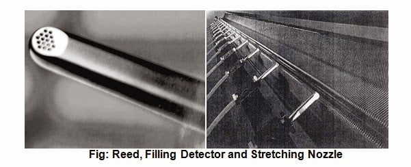
The reed 10 is tunnel-shaped, owing to the profile of the dents. With this configuration, the nozzles’ dynamic pressure is kept in the weft channel. As a result, the reed beats up the inserted pick at the fell of the fabric.
When the pick arrives at the right-hand end of the reed, it is monitored by weft detector 11. The weft detector, like the reed, is mounted in the sley. If the pick is too late or does not arrive at the weft detector, the optical control reacts, and the weaving machine shuts off.
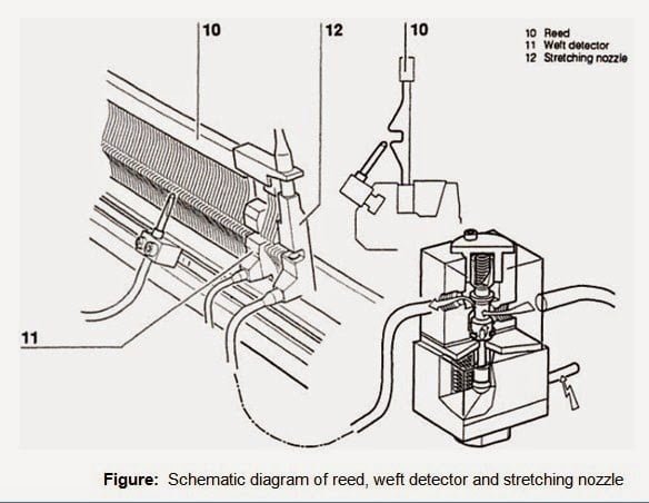
For some weft yarns, especially filament yarns, a stretching nozzle 12 is used. The stretching nozzle keeps the weft yarn tensioned after its arrival in weft detector 11. The air pressure and timing can be set individually for this function.
You may also like: An Overview of Water Jet Loom


Great beat ! I would like to apprentice while you amend your web site, how could i subscribe for a blog site? The account helped me a acceptable deal. I had been a little bit acquainted of this your broadcast provided bright clear concept