Study on Interlock Circular Knitting Machine
Last updated on September 5th, 2023 at 12:16 am
Introduction
There is four basic knitted structure required different types of machine to produce them. Theplain structure can be produce by single jersey circular knitting machine, where the cylinder with needle revolves on the stationary cam. The rib and interlock structure are required two sets of needles arranged in horizontally and vertically. The horizontal needles places on the groove of dial and the vertical needles grooved on the cylinder. Both cylinder and dial needles circulated around the stationary cam. Another type is purl structure, required special types of m/c and needles.

Objectives
- To know about the interlock m/c
- To know about the interlock fabric structure.
- To know about the cam arrangement of the m/c.
- To know about the knitting action of the interlock m/c.
- To know about the different needle timing of the interlock m/c.
- To know about the operation principle of the interlock m/c.
Interlock Structure
Originally, interlock was knitted almost solely in cotton on 20 gauge (needles per inch) machines for underwear, a typical weight being 5 oz per square yard (170 g per square meter) using 1/40’s s cotton, but from the 1950s onwards, 18 gauge machines were developed for knitting double jersey for semi-tailored suiting because the open width fabric could be finished on existing equipment. As the machines became more versatile in their capabilities, the range of structures became greater.
Interlock has the technical face of plain fabric on both sides, but its smooth surface cannot be stretched out to reveal the reversed meshed loop Wales be because the Wales on each side are exactly opposite to each other and are locked together. Each interlock patter row (often termed as “interlock course”) requires two feeder courses, each with separate yarn that knits on separate alternate to each other. Thus, odd feeders will produce alternatives Wales of loops on each side and even feeders will produce the other Wales.
It is a balanced, smooth, stable structure that lies flat without curl. Like 1×1 rib, it will not unrove from the end knitted first, but it is thicker, heavier and narrower than rib of equivalent gauge, and requires a finer, better, more expensive yarn.
As only alternate needles knit at a feeder, interlock machines can be produced in finer gauges than rib, with less danger of press-off. Interlock knitting is, however, more of a problem than rib knitting. Because productivity is half, fewer feeders can be accumulated, and there is finer tolerance. When two different-colored yarns are used, horizontal stripes are produced if the same colour is knitted at two consecutive feeders and vertical stripes if odd feeders knit on colour and even feeders knit the other colour. The number of interlock pattern rows per inch is often double the machine gauge in needles per inch.
The interlock structure is the only weft knitted base not normally used for individual needle selection design, because of problems of cylinder and dial needle collision. However selection has, in the past, been achieved by using four feeder courses for each pattern row of interlock, long and short cylinder needles not selected at the first two feeder courses for colour A being selected at the second two feeders for colour B. this knitting sequence is not cost effective.
M/C Specification
BRAND: FUKUHARA
MODEL: V 8ME42
SIZE: 30
SERIAL NO: 1352761
NO OF FEEDER: 84
COMPANY: PRECISION FUKUHARA WORKS. LTD
ORIGIN: JAPAN
Main Parts of the Machine
- Positive feeder.
- Tooth belt/ Timing belt.
- Driving wheel.
- On/Off key.
- Knot catcher.
- Tensioner & magnet.
- Storeer/Supplier.
- Feeder.
- Cylinder.
- Dial.
- Cylinder needle.
- Dial needle.
- Cylinder cam.
- Dial cam.
- Spreader.
- Take down roller.
- Batch roller/Cloth roller.
- Lycra attachment.
- Variable dia for quality pulley.
Machine Description
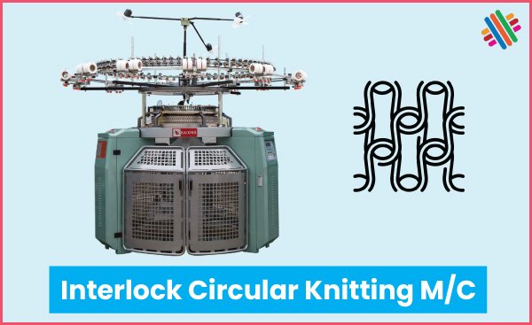
The yarn to fabric path diagram of interlock circular knitting machine is shown in Fig. which is described below:
In modern Interlock circular knitting machine, side creel is used. Cones are placed in the side stands in the cone holder. Through the suction pipe the yarn is passed to the feeder. Because of proper passing of yarn, the yarn is thrown by pipe with the help of air. In the middle path, the yarn crosses guide, disc type tensioner & sensor. There is a lamp with the sensor. It indicates the yarn breakage. The yarn is placed to the needle by the feeder. There is also nozzle, needle detector, fabric detector and regulator. The central lamp indicates whole condition of the machine. If the m/c is not properly ready to run, it will indicate. If any problem create like yarn breakage, low tension opened door, and then it will also indicate. There is an extra device which called LYCRA attachment to deliver the Lycra yarn shown in Fig.
There are two sets of needle is used. Cylinder needle and dial needle. Both cylinder and dial have two types of needle, namely short butt needle and long butt needle. Also there are two sets of cam in both cylinder and dial to operate individually the short butt needle and the long butt needle.
Driving Mechanism
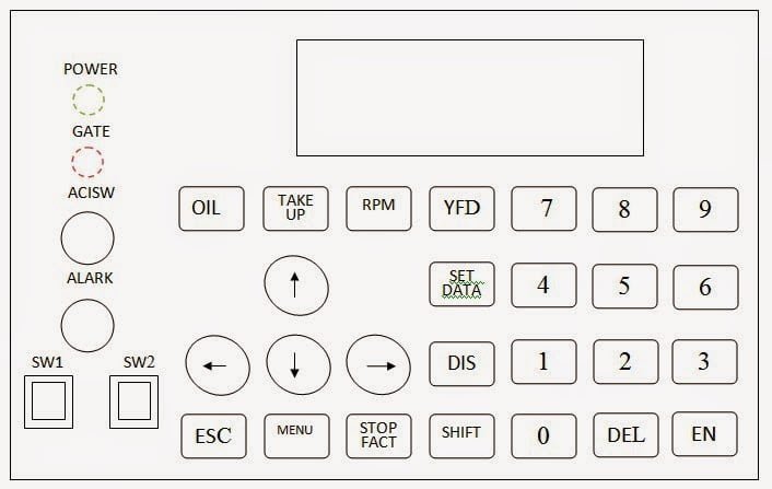
In interlock circular knitting machine there are two sets of needle namely cylinder and dial needle are placed at right angle to each other. The machine is operated by a main control unit. In control unit, there is a small monitor where all running action can be seen on this monitor. After inserting all yarn in the required feeder, the machine is run in inching motion to find out any fault. After resolving the fault, the machine may run in full speed. There is lot of switch having different function.

Interlock Setting of Cylinder and Dial
Front and top views of this setting (gaiting) are shown in Fig.03. In Fig.03 the grooves 1-6 of the dial Y are aligned directly opposite to the grooves 1-6 of the cylinder Z. as such, the cylinder and dial needles are also directly one opposite to the other.
Therefore at any given working point (feeder), cylinder and dial needles opposite to one another can never work at the same time, because they would collide while being cleared. Related to a working point (feeder), it is thus normal usage in interlock setting to work with-
- Dial needles in grooves 1, 3, 5,…..
- Cylinder needles in grooves 2, 4, 6, ….
- Dial needles in grooves 2, 4, 6,…..
- Cylinder needles in grooves 1, 3, 5, …
- Dial needles only
- Cylinder needles only
Working with an interlock setting therefore requires two sorts of needles in the cylinder and in the dial, and these have to be controlled and clear independently. One sort of needle is normally present in the grooves 1, 3, 5 … and the other needle sort in grooves 2, 4, 6 …. However, other needle combinations are also possible.
Interlock Cam System
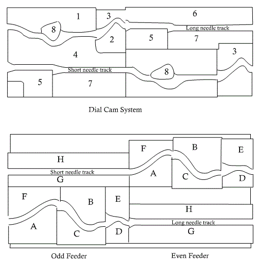
Fig. shows the cylinder and dial needle camming to produce one course of ordinary interlock fabric, which is actually the work of two knitting feeders. In this example, the dial has a swing tuck can that will produce tucking if swing out of the cam-track and knitting if in action.
The cylinder cam system
- A – Clearing cam which lifts the needle to clear the old loop.
- B, C – Stitch and guard cams respectively, both vertically adjustable for Varying stitch length.
- D – Up throw cam, to raise the cylinder needle whilst dial needle Knocks-over.
- E, F – Guard cams, to complete the track.
- G, H – Guide cams that provide the track for the idling needles.

The dial cam system
- 1 – Raising cam to tuck position only.
- 2, 3 – Dial knock-over cams (adjustable).
- 4 – Guard cam to complete the track.
- 5 – Auxiliary knock-over cam to prevent the dial needle re-entering the old loop.
- 6, 7 – Guide cams that provide the track for the idling needles.
- 8 – Swing type clearing cam, which may occupy the knitting position as shown at feeder 1 or the tuck position as shown at feeder 2.
Interlock thus requires eight cam systems or locks in order to produce one complete course, two cam systems foe each feeder in each needle bed. Basic cylinder and dial machines and flat-machines having this arrangement are often referred to as eight lock machines.
Production of Interlock Fabric
Interlock is produced mainly on special cylinder and dial circular machines and on some double system V-bed flat machines. An interlock machine must have the following:
1. Interlock gaiting, the needles in two beds being exactly opposite to each other so that only one of the two can knit at any feeder.
2. Two separate cam systems in each bed, each controllinghalf the needles in an alternate sequence, one cam system controlling knitting at one feeder, and the other at the next feeder.
3. Needle set out alternately, one controlled from one cam system, the next from the other; diagonal and not opposite needles in each bed knit together.
Originally, the interlock machine had needles of two different lengths, long needles knitting in one cam-track and short needles knitting in a track nearer to the needle heads. Long needle cams were arranged for knitting at the first feeder and short needle cams at the second feeder. The needles were set out alternately in each bed, with long needles opposite to short needles. At the first feeder, long needles in cylinder and dial knit, and at the second feeder short needles knit together; needles not knitting at a feeder follow a run-through track. On modern machines the needles are of the same length.
Conclusion
The rib and interlock are both double jersey knitted fabric. The interlock fabrics are heavier fabric than the rib fabric. This experiment will help us in our engineering life.
You may also like: The Needle: The Heart of Knitting


I simply wanted to thank you so much again. I am not sure the things that I might have gone through without the type of hints revealed by you regarding that situation.